
Before Side View
Before Side View

Before Front View
I bought my truck with the original Rochester Quadrajet carb on it. The Quadrajet had a divorced choke - basically a bi-metallic spring attached to the intake manifold with a linkage to the carb choke shaft. The link to the spring was broken, so it had been running with full choke. And the carb was in really poor condition.
I wanted to use a Holley-style carb because they are very tunable. I realize that electronic fuel injection runs really nice, and the prices are reasonable. But I wanted to keep a carb. The challenge is to get it working almost as well as fuel injection.
I wanted to get a 4150 series carb. My recommendation for a Holley style carb:
I got an SS-680-VS carb from Quick Fuel. This carb has some desirable features not typically found on a standard Holley carb:
To help with tuning, I used a vacuum gauge and a wide band oxygen sensor. The vacuum gauge is hooked to full manifold vacuum to help select a power valve and help with setting the idle A/F ratio. I had a single bung welded into my exhaust for an Innovate Motorsports LC-2 wide band data-logging oxygen sensor. I also have a SpeedHut Air/Fuel gauge in the dash that runs off an output from the LC-2.
For the fuel lines, I'm using a teflon-lined braided hose to deal with potential ethanol problems. This is Earl's Speed-Flex hose in a -6 AN size.
I'm using a Carter 4070 fuel pump. This is rated for 50 gallons/hour of flow, and 4-8 psi output. The engine I will be using would need about 35 GPH for prolonged full throttle.
There is a 100 micron filter before the fuel pump, and a 10 micron filter after the pump. Since I have a carb and not fuel injection, a 30 or 40 micron filter after the pump would be OK - the 10 micron filter is suggested for fuel injection. I might change the filter after the pump to a 30-40 micron filter, so the pump does not have to work unnecessarily hard.
I used a fitting directly off of the fuel tank, and a -6 AN bulkhead fitting to go thru the cab floor. I am not using any hose except Earl's Speed-Flex hose in the fuel system. If I used a non-braided hose, I would use Earl's Vapor Guard hose. Vapor Guard is not teflon-lined, but is rated for E85 and Methanol, so it should be just about as good as a teflon-lined hose. Vapor Guard comes in a Carb & EFI version with different pressure ratings.
After the fuel pump and filters, I have a Holley 12-803 fuel pressure regulator set to 4 to 5 psi. I added a gauge in the line to see the actual pressure.
To prepare the carb for 10% ethanol fuel, the float bowl needle valve, the diaphragm for the accelerator pump, the O-ring around the outside of the needle & seat, and the O-ring around the float bowl sight glass need to be addressed. From the factory, the Holley has these made from rubber and will only last 1-2 years before they start to deteriorate.
Most needle & seats that have a black polymer insert from the last few years are probably Viton, not rubber. But to be sure, I will replace this. I'm using a .110" diameter needle and seat from AED with a Viton-tipped needle.
For the accelerator pump diaphragm, I'm using a Holley part made from Viton-GFLT. This has to be replaced, since it is made from rubber and is gravity fed from the float bowl and will drip fuel on the intake manifold.
For the two O-rings, I'm using Fluorosilicone O-rings from The O-Ring Store. The O-ring for the outside of the needle & seat is P/N FS70008 - this has an ID of 3/16", an OD of 5/16" and a thickness of 1/16". The O-ring behind the fuel bowl sight glass is P/N FS70014 - this has an ID 1/2", an OD 0f 5/8" and a thickness of 1/16". The O-ring around the needle & seat absolutely needs to be replaced, since it is under the pressure from the fuel pump and will flood the float bowl and dump fuel in the carb. The O-rings for the sight glass are not as critical, since they do not regularly leak, but I am replacing them since they are just a few cents.
I plan to tune the carb, but going more in depth than just changing out the primary & secondary main jets. When I tune the metering blocks, I will need threaded locations for the idle feed restrictors (IFRs), power valve channel restrictors (PVCRs) and emulsion bleeds. The emulsion bleeds need to be tapped at about a 45 degree angle, and the PVCRs need to be tapped at an angle and also have a counter-bored area for the head. So I think it is easier to get new metering blocks with these already threaded instead of drilling and tapping the original Holley metering blocks. I will still have to tap the locations for the IFRs, but they are not at an angle and do not need a recess for a head.
The Quick Fuel SS-680-VS has a set of billet metering blocks that can also be purchased separately - P/N 34-111, a combo of the 34-8 primary and 34-66 secondary metering blocks. The Quick Fuel metering blocks have 0.031" primary and 0.033" secondary threaded-in jets for the IFRs, and the primary metering block has 0.050" threaded power valve channel restrictors (PVCRs). The emulsion bleed locations can be tuned - they are 0.028" drilled holes, but have threads if you want to block them off or change the bleed sizes.
I modified the Quick Fuel metering blocks:
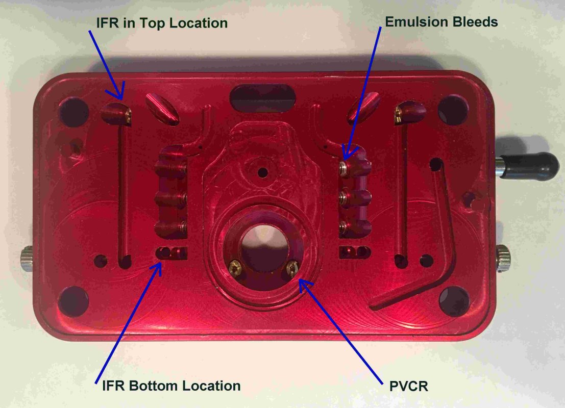
Metering Block Before.
A tap has cleaned up E-Bleed threads.
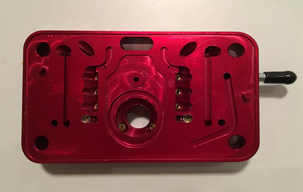
Metering Block After.
Modified with IFR Moved to Lower Position.
| Parameter | Quick Fuel (stock) | Quick Fuel (tuned) |
|---|---|---|
| Booster | Down-Leg | Down-Leg |
| Idle Mixture Screw | 1 1/2 turns out | 1/2 turn out |
| IFR | 0.031" & 0.033" | 0.031" |
| Primary Jet | 68 | 68 |
| Secondary Jet | 78 | 76 |
| Secondary Jet Extension | Yes | Yes |
| PVCR | 0.050" | 0.049" |
| Emulsion Bleed Size & Number | 0.028", 3 | 0.028", 2 |
| Power Valve | 6.5 | 6.5 |
| IAB | 0.070" | 0.070" |
| HSAB | 0.028" | 0.028" |
| Accelerator Squirter | 0.031" | 0.031" |
| Accelerator Cam | Pink, #1 | Pink, #1 |
| Accelerator Pump Size | 30 cc | 30 cc |
| Vent Whistles | Yes | Yes |
| Vacuum Secondary | 1/2 Turn Out | 1/2 Turn Out |
The Quick Fuel tune is with the fuel 1/2 way up the sight glass. My location is about 1000 ft above sea level, with 30-70% humidity and 20-90 degrees F.
My other setup parameters will be:
I need to make sure that the timing marks on the damper are correct by checking TDC of the #1 cylinder against the damper markings.
The only HEI distributors that several internet forums say are reliable are Performance Distributors (DUI), Pertronix, and GM.
The truck already had an HEI distributor when I bought it, but I wanted to replace it to make sure it was OK.
I got a new-old-stock (NOS) GM distributor, P/N 1103375
This distributor came with a distributor cap with aluminum terminals, and I replaced it with a Standard Motor Parts cap with brass terminals, P/N DR-450
I'm using a rotor from Standard Motor Parts, P/N DR-318
I got a NOS GM ignition module, P/N 1875990
The coil in the cap has red, yellow and black leads, and the distributor gear fits on a .491" diameter shaft.
For timing, I want no mechanical advance until 1000 RPM, and 20 degrees mechanical advance at 2800 RPM. The vacuum advance should have somewhere between 10 and 12 degrees advance.
For the Blueprint CT350 engine, they recommend 32 degrees of advance (mechanical & static timing).
The distributor is installed and adjusted with the vacuum line temporarily taken off, and timing is set to about 12 degrees BTDC at an idle of 600-700 RPM.
For final distributor tune, the vacuum line will be put on ported and manifold vacuum, to see which one performs better. Generally this can be determined if there is a stumble off of idle or not. David Vizard says that manifold vacuum works better for idle and gas mileage in his book on this - see reference at bottom of this page.
Holley recommends that the float bowls should be set to have the fuel level near the bottom of the sight window. Quick Fuel recommends setting the fuel level at the middle of the sight glass. Since both of these brand's fuel bowls have the sight glass window at the same height, you can probably set either brand at whichever height you want. I plan to set the float to have the fuel in the middle of the sight glass.
I used a vacuum gauge to measure manifold vacuum at different points, in order to select a power valve. I measured 15" at idle in Drive. At steady state cruise on level ground, I measured 12" at 35 MPH, 12" at 45 MPH and 11" at 55 MPH. The vacuum does not go below 9" unless I start to really accelerate. At wide open throttle (WOT) I still have 3" of manifold vacuum.
There are a few ways to figure the best power valve size:
I plan to be a little conservative and use a 6.5 power valve.
The idle circuit is controlled by the idle mixture screws and the idle speed screws. The IFRs can change the idle mixture, but this will be dealt with in the next step. It is important to not have more than 0.020" of the primary transition slot exposed at idle, or the engine starts to run on the transition circuit.
With the engine at operating temperature, I will shut off the engine and bottom all 4 idle mixture screws and open them up 1 turn. I will then start the engine and adjust the mixture screws equally to achieve an A/F ratio of 14.0 to 14.7, maybe requiring 13.5 for engines with long duration camshafts.
A vacuum gauge helps here - it is best to tune for highest vacuum, while keeping the A/F ratio in the desired range. With a mild cam, it is reasonable to expect that the A/F ratio can be set close to 14.7. Set the throttle speed to the lowest stable speed it will run - this is probably 700 in drive and 800 in park. I will repeat finding the correct A/F ratio and setting the idle speed until they are both set OK. This should be optimized with the transmission in drive. Idle A/F ratio is all about the idle mixture screws and keeping the primary throttle plate with 0.020" of the transition slot exposed. If the primary throttle stop gets adjusted, make sure the accelerator pump arm is adjusted to take any slack out of it and allow a 0.015" feeler gauge to pass between the arm at WOT.
The transition circuit is controlled by the IFR jets and idle air bleeds (IABs). The transition circuit comes on when the throttle is opened coming off of idle, and as long as the throttle is gently opened, usually runs the vehicle to 2000-2500 RPM. With the engine at operating temperature, under light cruise on level ground or a slight downhill, go from 1400-1500 to 2000-2500 RPM and look at the A/F ratio - the target is 14.3 to 14.7. If it is always too rich or too lean, change the IFRs. Smaller IFRs make the A/F ratio leaner, and larger IFRs make the A/F ratio richer. If the Air-Fuel ratio goes lean to rich as the RPMs get higher, put in smaller IABs - rich to lean means bigger IABs. The IFR is the coarse adjustment, and the IAB is the fine adjustment for A/F ratio in the transition circuit. If the IABs or IFRs are changed, readjust the idle mixture screws again for the correct A/F ratio at idle.
The primary circuit is controlled by the primary main jets, PVCRs and the primary high speed air bleeds (HSABs). The power valve also changes the primary circuit tuning.
A good initial way to select the PVCR size is to take the area of the primary main jets and add the area of the PVCRs. This should equal the area of the secondary main jets. An example - with 69 primary jets (0.070" diameter) and 74 secondary jets (0.081" diameter), this works out to 0.040" PVCRs. But the jets might be 74 primary (0.081") & 86 (0.101") secondary, which works to a 0.060" PVCR.
With the engine at operating temperature, put a vacuum gauge on the manifold port of the carb and gently go from 1500 to 4000 RPM or so, making sure that the vacuum is more than the power valve is rated for, and that the secondaries are closed. This allows you to see what the primary main jets are doing. The goal is to have the air/fuel ratio about 14.7-15.3, and can go as high as 16.0:1. Adjust the primary main jets as needed.
While evaluating the primary main jets, see if the A/F ratio is relatively flat. If things are too rich at a higher speed, the primary HSABs should be increased in size - if too lean at higher speed, decrease the HSAB sizes. If the A/F ratio has the slope corrected with the HSABs, but there is a curve left, the emulsion bleeds can be used to flatten out the A/F ratio. Again, make sure that the secondaries are disabled and that the manifold vacuum never gets below the power valve rating during these tests. This sets the "cruise" A/F ratio, and can greatly improve your gas mileage.
Now we set the PVCR size. With the secondaries disabled, run with WOT (wide open throttle) from about 1500 to 4000 RPM - don't go above 4000, because the primaries alone cannot supply enough fuel/air above these speeds. This is where we are looking for optimized A/F for power - about 12.6-13.3, although anywhere from 12.2 to 13.5 is fine. Adjust the PVCR size to get close to this number, again using WOT.
The secondary circuit is controlled by the secondary vacuum spring, the secondary HSABs and the secondary main jets. The secondary vacuum housing controls when the secondary throttle plates open, and the secondary jets and secondary HSABs control the amount of fuel.
With the engine at operating temperature, go 2500-5500 RPM, with wide open throttle (WOT). The goal is to be at a 12.6-13.3 A/F ratio, although anywhere between 12.2 and 13.5 is fine. If too rich or lean at 4000 and above, adjust the secondary jets. If too rich or lean from 2500-4000 RPM, adjust the secondary HSABs. Bigger HSABs lean the A/F ratio. The secondary vacuum housing will be adjusted later.
The accelerator pump circuit is controlled by the accelerator pump size, the squirter and the accelerator pump cam. The Quick Fuel carb comes with a 30 cc accelerator pump, has a pink accelerator pump cam in the #1 hole, and a 0.031" squirter. A 50 cc pump is available, but I plan to stay with the 30 cc pump. I plan to use the 0.031" squirter that came stock with the carb.
While driving, give a 1/3 throttle and full throttle stab to evaluate the accelerator circuit. Adjust cam and squirter to get a brief 13.8 A/F ratio for light acceleration, and 12.5 A/F ratio for full acceleration for a second or two. If the mixture is too rich (10.0 A/F ratio or so) right after full throttle, try using a smaller-lift accelerator pump cam or retarding the pump cam by moving it from 2 to 1 on the throttle shaft. The stock pink cam in the #1 hole might be fine, or I may go to the #2 hole in the pink cam. The blue accelerator pump cam might also be worth trying. If there is a lean spot a half second to a second after flooring the throttle, the accelerator pump nozzle (squirter) may be too big. Try reducing the accelerator pump squirter nozzle size, which extends the duration of the accelerator pump's discharge - then there should be a smoothing or flattening of the A/F ratio after flooring the throttle.
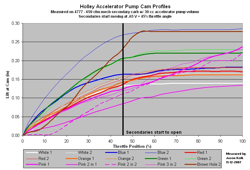
Holley Pump Cam Chart
FYI - The brown & yellow cams are for use only on a 50 cc pump - these generally will hold the 30 cc pump body open after using it once. For a given cam, using it in the #2 hole generally gives more fuel volume and at a higher rate than using it in the #1 hole position.
The Quick Fuel carb has a screw adjustment on the vacuum secondary housing. If the secondary side opens too quickly, the engine will bog. If the engine doesn't hesitate or bog under acceleration, the secondaries could be opening too late. Starting with the factory setting (1/2 turn out) accelerate at WOT. To determine where the correct opening point is, you need to keep adjusting the screw 1/4 turn out and make another WOT run until you get a bog, then turn the screw in 1/4-turn. Turning the screw "in" slows the opening rate, turning it "out" makes the secondaries open sooner.
Emulsion bleed tuning is considered an advanced tuning area, and is for fine tuning. The emulsion bleeds help tune the A/F ratio when the carb is running on the main jets.
The Quick Fuel billet metering blocks have 3 emulsion holes per barrel. The top emulsion bleed affects the bottom of the airflow range, the middle affects the middle, and the bottom affects the top. Making a bleed bigger thins the mixture, and making it smaller richens it. I'm starting by drilling all the emulsion bleeds to 0.050", blocking off the middle emulsion bleed with a set screw, and making bleeds for the top and bottom positions that have a 0.028" hole drilled in them. The set screws are brass 6-32 that are 3/16" long.
The electric choke housing can be rotated clockwise or counter-clockwise to make the choke turn off earlier or later. The amount of the choke is controlled by the choke fast idle screw.
The fast idle screw can be adjusted with a 1/4" open end wrench, with the engine off and the throttle held wide open. The fast idle screw should be adjusted to get 1500-1600 RPM when the engine is cold.
Some people rotate the housing to a "Summer" and "Winter" setting, since colder weather requires more choke, and warmer weather does not require as much choke.
I may need to add a fast idle solenoid to the carb to add additional idle speed when the air conditioning is on - Holley P/Ns 46-74, bracket 20-9 and lock nut 26-57. The lock nut may come with the solenoid.
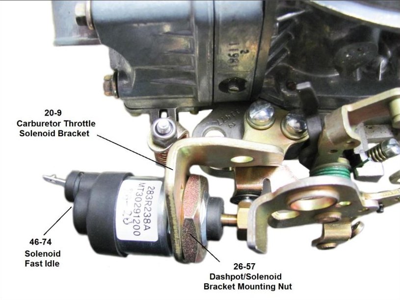
Fast Idle Solenoid