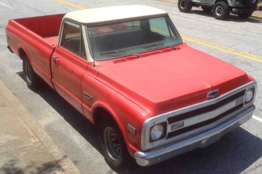
Before Side View
Before Side View
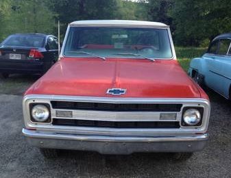
Before Front View
The original wiring harness was in good shape. There were splices around the radio, the alternator, the distributor and the starter. But I wanted to add a few devices, so I put in an American Autowire Classic Update wiring harness.
From the original wiring harness, I wanted to remove or modify a few things:
I wanted to add a few things:
The lighting is stock, with 3 changes:
The starter is a gear reduction starter from DB Electrical.
The original washer pump on these trucks are notoriously weak. There is a rebuild kit, but it does not last that long. I put in a washer reservoir & pump from a 1994 Chevy C1500 truck. To wire the washer motor, disconnect the yellow and dark blue wire from the connector that goes to the washer motor under the dash. The yellow wire is +12 when the ignition is on, and the dark blue wire gets grounded when the washer switch is pushed.
The original alternator was already changed to a 10SI alternator with internal voltage regulation when I bought the truck. I'm not sure what the amperage output is, but most likely it is 72 amps. Since I am adding electric cooling fans and an electric fuel pump, I am concerned with power output at idle. I changed the alternator to a 140 amp Tuff Stuff CS-144 when the serpentine belt drive was installed. The "exciter" wire to the distributor may need a diode or resistor inline, but mine did not. The advantage of the CS144 is that it puts out 50 amps at idle, and is very reliable. I need that power output at idle to run the electric fans.
The original battery cables were 6 gauge. There was a 16 gauge wire going from the positive battery post to the junction block, with a 20 gauge fusible link inline. I got new 1/0 gauge battery cables from Custom Battery Cables. The positive cable is 62" long with a 90 degree bent 3/8" HD lug for the starter connection, and a 12" 4 gauge pigtail with a regular 1/4" lug going to the junction block. The negative cable is 42" long with a 3/8" HD lug that connects to the engine block, and a 14" long 4 gauge pigtail with a 5/16" lug that connects to the radiator support near the battery.
There originally was a 12 gauge wire from the alternator to the junction block. The American Autowire Classic Update kit comes with a 6 gauge wire from the alternator with a 3 mm fusible link, although I am not going to use the fusible link. When I put in the CS144 alternator, I put in a 4 gauge wire from the alternator to a 150 amp circuit breaker mounted near the junction block to replace the original 12 gauge wire. Then there is a 4 gauge wire with 1/4" lugs on both ends going from the circuit breaker to the junction block. The alternator has a .21" stud (an unusual size), so this wire will have regular 1/4" ring terminals on both ends. This wire goes across the top of the radiator.
There is a 30 amp circuit breaker going from the junction block to the main wiring harness. The 150A alternator breaker and the 30A main harness breaker replace the function of the original fusible links.
The American Autowire harness already has the ammeter wiring removed, and has provisions for the dash gauges. I'm not using the tan brake warning switch wire under the hood, the tan brake warning light wire in the dash (no printing), or 3 (yellow, purple and purple/white) wires intended for a VSS option under the hood. There is a light blue wire coming from the rear body kit that is intended for a 3rd brake light that I will not use. In the instrument cluster kit, connector H with a yellow and purple wire is not used - this is for an electronic speedometer. And there is a brown Park Lamp wire in the instrument cluster kit that is used to dim the panel lights when the headlights are on - this is needed for a Dakota Digital dash, but not for me.
The orange wire in the American Autowire harness is intended for a cooling fan relay. This is used to energize the electric choke relay, then to the fan speed controller. The fans are controlled with an Auto Cool III PWM fan controller. There are two 40 amp circuit breakers, feeding two Spal 13" fans with 10 gauge wire. The shroud for the fans came from eBay.
The Vintage Air A/C system came with a binary switch. Basically the under dash system decides when it wants the A/C compressor to come on, and sends 12 volts to the compressor to energize the A/C clutch. Except the 12 volt signal goes through a binary switch on the way to the compressor. If the pressure in the high pressure side of the A/C is above about 30 psi and below about 406 psi, it energizes the A/C clutch - otherwise the clutch is not energized if there is no refrigerant (too low pressure) or a blocked expansion valve (too high pressure).
But I am using an electric fan, so I am using a trinary switch. A trinary switch has 4 connections - 2 of them are wired in exactly like the binary switch. The other 2 connections are used to turn the fan on when the A/C system is working kind of hard. This connection closes when the high side A/C line has 256 psi or more. On this connection side, one line goes to the fan relay, and the other side is grounded to the frame. Since I am using an AutoCool module to control the fans, I connected this to the "F/S" (or fail safe) connection to ground this connection and turn the fans on.
The orange wire in the American Autowire harness going to the cooling fan relay is also run to a relay for the electric choke. A 30 amp relay in a holder with a 10 amp circuit breaker comes from the junction block to the electric choke.
The dark blue wire in the American Autowire harness that is intended for a fuel pump will be used to switch power to the electric fuel pump. I've added a security feature to the fuel pump wiring. Since the Vintage Air A/C system does not use the fan switch in the dash, I'm using it to enable the fuel pump when the fan switch is in the "correct" position. The dark blue wire in the wiring harness goes to a new "fuel pump" relay to the +energize terminal, and coming off the -energize terminal from the relay is a wire that goes to the fan switch on the dash. The other side of the fan switch goes to chassis ground. The common terminal of this relay gets power from the junction block through a 20 amp circuit breaker and the normally open terminal goes to the electric fuel pump.
So the under hood wiring gets a little busy:
I've installed a GPS tracking device to keep track of the vehicle - a Trackimo system. I wired into an always-on-power connection to power and charge it. If the vehicle battery is disconnected, the internal battery in the Trackimo will last at least 2 weeks to power it. My Trackimo system is an older model - The Trackimo models today are about $50. They cost about $120/year for service. My module uses 3G cellular, Bluetooth and Wifi, but the newer models use 4G (with 3G and 2G as backup) and Bluetooth and Wifi. The vehicle charging kit is $20. There is a 3500 mAh battery ($50 with waterproof case) - this gives 12-21 days of 1 minute updating. The charger draws 15 watts. It has move and geo-fence alerts, and sends an alert when the battery gets to 20%. It also has a free Android & iPhone app.